How to Draw a Manual Line in Arcmap
Elevation profiles were referred to as profile graphs in previous versions of ArcGIS Pro as they were the closest counterpart to elevation profiles in ArcMap. ArcGIS Pro 2.7 has introduced a new Elevation Profiles tool which will be more familiar to ArcMap users.
In this and the next blog, we'll explain the differences between the two in ArcGIS Pro 2.7 – Elevation Profiles and Profile Graphs.
The flowchart below should help get you pointed in the right direction. Your project requirements and desired outputs will be the greatest factors in determining which of the tools to use. We'll start by looking at Profile Graphs.

Profile Graphs
Profile Graphs require a Z-enabled feature class and the 3D Analyst extension. You can either:
- Use an existing Z-enabled (3D) line feature class;
- Convert a 2D feature class to 3D, or;
- Create a Z-enabled line feature class from the Ready-To-Use Elevation Profiles. This is explained in more detail below.
If you're using a Z-enabled line feature class (1), you're good to go – see the Creating a Profile Graph section below. If you need to convert 2D features to 3D or update the Z-values in a 3D feature class (2), first use the Interpolate Shape or Update Feature Z tools, which both require an elevation surface and the 3D Analyst extension, before creating the graph.
Ready-To-Use Elevation Profiles
If you don't have your own elevation surface or 3D lines to use, you can use the Ready-To-Use Elevation Profile to create a Z-enabled line:
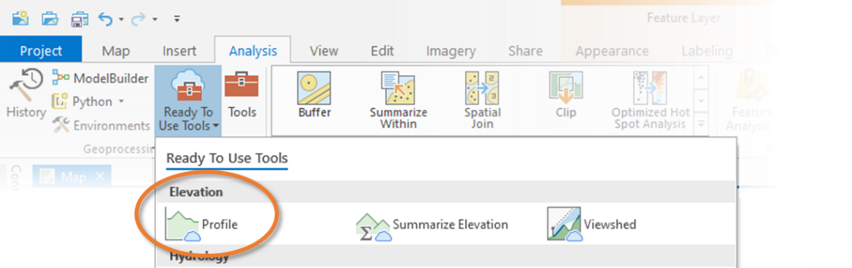
- From the Analysis tab select Ready-to-Use Tools > Elevation > Profile.
 2. For Input Line Features, select the line layer you wish to use or, if you want to draw your own lines, create and sketch lines directly from the Input pane.
The elevation Z-values will be stored with each vertex of the line. If you want more vertices – and therefore more data points – for your profile, use the Maximum Sample Distance parameter to specify the greatest distance between vertices along each line.

The Ready-To-Use tool runs directly on ArcGIS Online using Esri's authoritative elevation data to interpolate the Z-values along the input lines. The tool is free to use with an ArcGIS Online account without spending service credits. It is not accessible on a local ArcGIS Portal implementation, or without access to ArcGIS Online hosted services. The default DEM resolution comes from 90-metre SRTM data, but higher resolutions are available in some areas.
The Ready-To-Use Elevation Profile tool does not output your elevation profile directly. Instead, the output line features, now complete with elevations, can be used to create a Profile Graph following the steps below.
Creating a Profile Graph
- With a 3D line layer in your map, right-click the layer name in the Contents pane, then select Create Chart > Profile Graph.

The new chart will appear in the Contents pane as a sub-layer of the 3D line layer just below the symbology. It opens in a separate view tab in the ArcGIS Pro window.

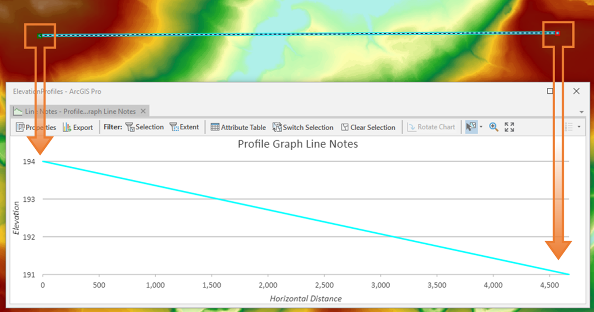
To create this graph, each vertex's Z-value is plotted at the distance along the line (M-value). It does not need to use an elevation surface because the Z-values are already in the vertices. This means that the detail of the profile depends on how many vertices there are in the features. For example, graphing a line with only two vertices – start and end points – will create a profile graph with only those two points. If you only need to plot the overall change of elevation from start to end, this may be a good solution.
To see elevation changes in between, add more vertices. For each vertex added, another point is plotted on the graph.

Use the stream tool to add vertices at intervals as you move your cursor.

Using Editing or Geoprocessing tools to simplify or densify vertices on your line features will also have the same effect on the profile graph.
2. To set the elevation source for new features open the Edit tab and find the Elevation group. Use the Mode drop-down to select "Surface". The source drop-down should default to "Ground."

As you add or move vertices, the Z-values will automatically be interpolated from the Ground elevation surface. Otherwise, the default value of 0 will need to be manually changed for each vertex. The lines are plotted from start vertex to end vertex, so if a line appears backwards, reverse the direction of the line.
3. Customize the graph by clicking the Properties button, e.g. to set distance and elevation units, graph extents, labels, and graph colours.
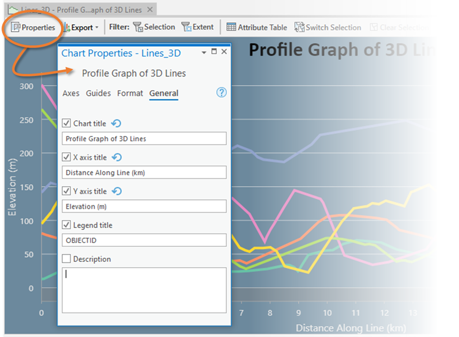
The colours of the profile lines themselves are based on the layer symbology, so edit your symbology to change those line colours.
The Profile Graph view is interactive – selecting a line on the graph selects it on the map. Turn individual lines on and off by clicking them in the legend, or filter the graph by current selection or map extent.
The graph can be exported in SVG, PNG, or JPG formats. It is saved with the layer in your project, so you can always come back to it later for editing or to export again.
Here you can find a summary of the differences between Elevation Profiles and Profile Graphs.
Stay tuned for part II – Will be shared next week!
Posted by Alex Rexroad, GIS Consultant
How to Draw a Manual Line in Arcmap
Source: https://www.exprodat.com/blogs/creating-elevation-profiles-in-arcgis-pro-part-i/
0 Response to "How to Draw a Manual Line in Arcmap"
Post a Comment